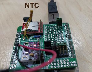
NTC thermistor; arduino
Introduction
Theory
Electronics

The thermistor is connected in series with a resistor whose job is to limit the current. Thus, the total resistance of the circuit is
The Arduino can read the incoming voltage of analog input pin. ***At the moment I do not have the circuit, so I don't know what Arduino is reading***
Assume, Arduino reads the voltage over resistor . We know that the current through both resistors is same. Thus we have
Because , we get
or
We may use either of those two in the program, but if we use the first one that needs to be converted separately to in spreadsheet or in Python script. So, it needs more post processing but is faster and simpler in the satellite.
The measure value gives the temperature. Of course, it needs to be scaled. But that is not a problem.
The NTC is connected to Arduinos A0 pin. Check it! The other wire is at +5V. So, we should read A0 voltage.
Calibration
Simple but effective linear calibration can be done by using two known temperatures; eg room temperature and fridge temperature. Measure the in both situations and create a function of line through both points.
Note that many spreadsheets can do the slope estimation effectively using built-in functions.
Calibration using Steinhart--Hart equation
The Steinhart--Hart equation is complicated but more accurate model of the resistance of a (NTC) semiconductor at different temperatures. It says:
where
- is the temperature in Kelvins
- is the resistance measured
- and are the coeffiecients. Because there are three coeffients, we need to have at least three measuring points.
See thinksrs.com/downloads/programs/therm%20calc/ntccalibrator/ntccalculator.html
Code
Simple, but effective. Don't make complicated things in Arduino: get the raw data and analyze data afterwards.
.
float Vin=5.0;     // [V]
float Vout=0.0;    // Vout in A0

void setup() {
  Serial.begin(9600);
  pinMode(0, INPUT);
}

void loop()
{
  Vout=Vin*((float)(analogRead(0))/1024.0); //

  Serial.println( Vout);

  delay(100);
}
Exercises
- Use the colors on and deduce it resistance
- Apply a multimeter to read its resistance.
- Use a voltage and current meter and employ Ohm's law to calculate the resistance.
- Warm the sensor by putting it
- under a finger
- close to the radiator
- in the fridge; not really warming but. . .
- hot (or warm) water
- Calibrate the readings using Spreadsheet or Python!


